Getting Started
MonkeyBUS
So, you’ve brought the MonkeyBus. Good choice and thank you. The MonkeyBus development board for the PIC18F14K50. It ships with a test program and a bootloader from Microchip. Before you can dive in and start to work on it, best to line your ducks up and do the following:
Hardware
You will need the following hardware
- The MonkeyBus
- Mini USB cable
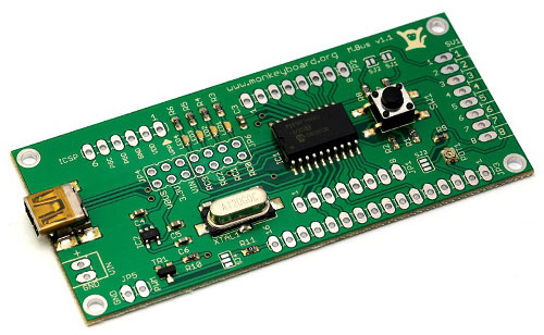
The MonkeyBus development board has three jumper switches. When powering the board with USB, use the jumper switch to select between 5V (VBUS) or 3.3V from the USB power. When using VIN put the jumper on the VIN position.
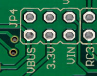
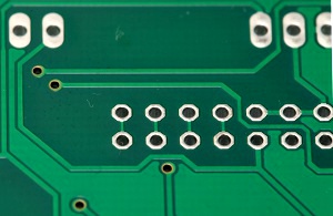
MonkeyBUS PIC18F14K50 development board ships with all pin headers however, not soldered on. This is done intentionally so that the user is free to place the pin header on either side of the PCB to suite their project. Also note that the LED jumpers are shorted (linked) by default. If those pins need to be input, cut the tracks on the bottom of the board (shown below). A jumper can be used to switch between LED and input if required.
SW1 is an on board switch linked to VPP and RA3. Pressing SW1 will set RA3 input to LOW. Some PIC18 examples from Microchip use this button to activate an action such as a keypress or other functions. The SW1 switch is more frequently used as a method to activate the onboard bootloader. Power cycle the MonkeBUS while holding down SW1 will set the PIC18 into bootloader mode. The following section explains how to load a firmware onto the PIC18 using the onboard bootloader.
Software
Download the following software:
Free IDE MPLAB from Microchip
MPLAB C for PIC18 v3.40 Standard-Eval Version
Microchip Solutions v2011-07-14
Once all above softwares are installed, you are ready to start a project using MPLAB IDE. Simply open an example project and compile.
Programming the MonkeyBoard
Under the Microchip Solutions v2011-07-14\USB\Device - Bootloaders\HID directory, run HIDBootLoader.exe. Power cycle MonkeyBoard while holding down SW1. This will put the board into bootloader mode.
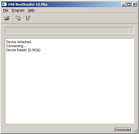
Press the open button or File->Import Firmware Image and locate the HEX file of the project you have just compiled.
Press the download button to flash the device. Press to reset button or Program->Reset to reset the device. The program will run automatically.
PC Connection Via USB
The MonkeyBUS can communicate with the PC via the USB port. The data is routed through the onboard USB stack and emulates RS-232 communication. To use MonkeyBoard with USB communication, install mchpcdc.inf file on the host PC:
-
1. Create a folder named, HPCINF, anywhere on the host PC’s hard drive.
2. Locate the mchpcdc.inf under Microchip Solutions v2011-07-14\USB\Tools\USB CDC Serial Demo\inf
3. Copy the content of the inf folder to HPCINF folder created in step 1
4. Connect the board to the PC and power up the board.
5. On Windows start bar press Start then right click on Computer and select Properties
6. Click on Device Manager and you will see driver is not found for CDC RS232 Emulator Demo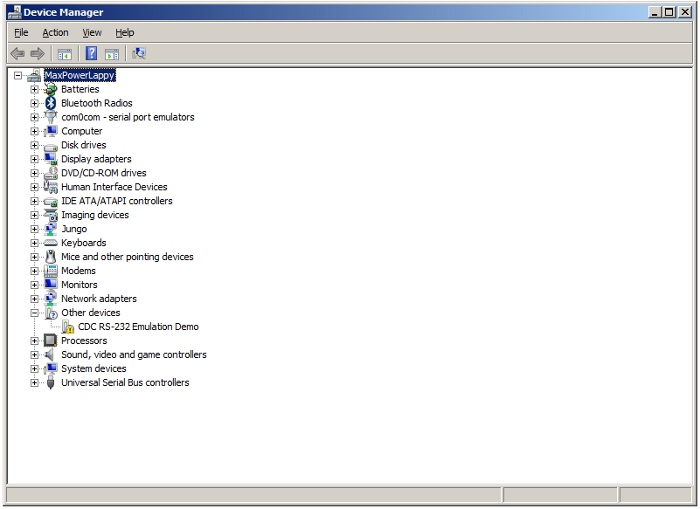
-
7. Right click on the CDC RS232 Emulator Demo and select Update Driver Software
8. Click on “Browse my computer for driver software”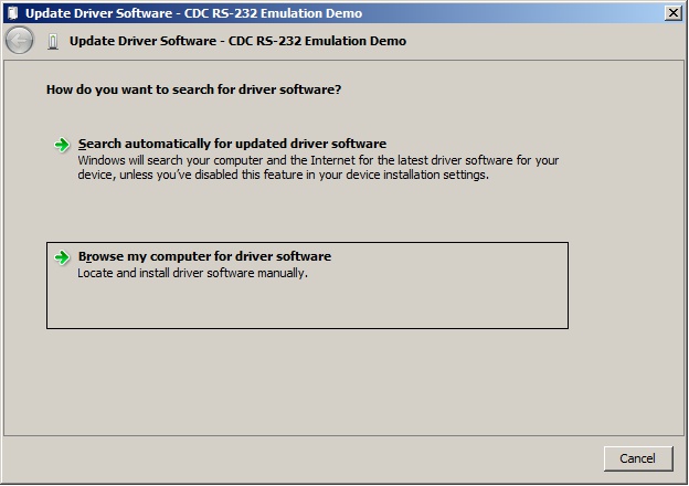
-
9. Locate the .ini file inside the NPCINF (created in Step 1) and click Next. The following screen will appear.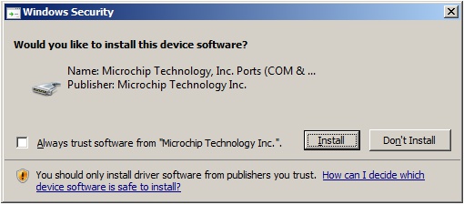
10. Press Install to finish off the process and close dialog box and device manager.
And it is done!
Downloads
MonkeyBUS User's Guide
PIC18F14K50 Datasheet
MonkeyBUS Schematics


