USB Serial to HD44780 LCD

Description
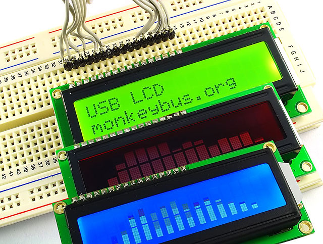
HD44780 based character LCD is a de facto industry standard LCD that is used in many designs such as clocks, robots and microcontroller boards. It is readily available from most electronic stores and EBay. Although this LCD is relatively easy to use, however interfacing with this LCD normally requires 6-10 IO pins for 4 bit and 8 bit mode respectively. With most PC no longer built with a parallel port, interfacing with this LCD requires a USB / Serial to LCD interface.
In this tutorial, we will explore the idea of using MonkeyBUS (PIC18F14K50) microcontroller board to translate virtual serial port on a USB port to HD44780 parallel interface.
Features
Translate serial command to HD44780 parallel command
- PWM controlled LCD back light
- LCD Smartie supported
- Direct LCD pin to pin plug-in
Parts & Tools List
- MonkeyBUS microcontroller board
- 16x2 HD44780 character LCD
- Hyperterminal or any terminal program
- MPLAB IDE v8.76 if you like to change the source code
Hardware
Setting MonkeyBUS
Since we need MonkeyBUS to run on USB, we could just power up the board from USB power. MonkeyBUS has a built in 10K potentiometer that can be used to set the LCD contrast and also a PWM output that could be used for controlling the brightness of the LCD backlight.
Setting up MonkeyBUS is just 3 easy steps, set the 3 jumpers as follow.
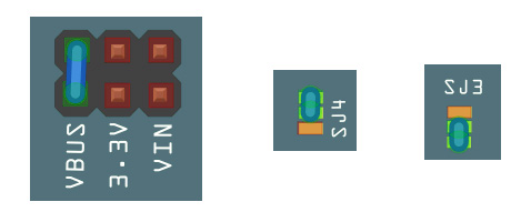
1. Jump VBUS
2. Jump 1-2 of SJ4 to connect PWM to control the LCD backlight
3. Jump 2-3 of SJ3 to connect 10K potentiometer to the LCD contrast PIN.
LCD Display
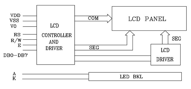
Most internal part of the standard HD44780 LCD displays looks like the following block diagram.
LCD Interface pin description
| Pin No | Symbol | External connection | Function |
| 1 | Vss | Power supply | Signal ground for LCD (GND) |
| 2 | Vdd | Power supply | Power supply (+5V) |
| 3 | Vo | Power supply | Contrast adjust via potentiometer |
| 4 | RS | MPU Logic | Register select |
| 5 | R/W | MPU Logic | Read/write select |
| 6 | E | MPU Logic | Enable signal |
| 7-10 | DB0 - DB3 | MPU Logic | Four low nibble bi-directional three-state data bus lines |
| 11-14 | DB4 - DB7 | MPU Logic | Four high nibble bi-directional three-state data bus lines |
| 15 | LED+ | LED backlight power supply | LED anode (+4.2v) |
| 16 | LED- | LED backlight power supply | LED cathode (GND) |
The power requirement of the LCD is +5V DC, however there are some newer generation only requires +3V DC. The contrast adjustment of the LCD is control via Vo by tying this pin to a certain voltage level. The LCD has to 2 basic registers, COMMAND and DATA register. By setting the RS pin low, the LCD will switch to the COMMAND register and when the RS pin is high it will switch to the DATA register.
Although a more elegant way to control this LCD is using both the READ and WRITE mode, however due to simplicity in implementation, most application will just implement the WRITE mode by connecting the R/W pin to low.
DB0 – DB7 are the data bus’s pins. To use this LCD in 4 bit mode, only the high nibble (DB4 – DB7) is used, 8 bit mode requires the low and high nibble operate at the same time.
Once the RS, R/W and data bus are set, a strobe (low – high – low) signal to the ENABLE pin will push or pull the data in or out of the LCD controller.
Connections to MonkeyBUS
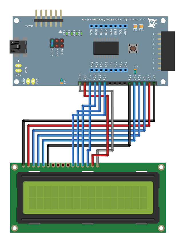
MonkeyBUS is designed to be able to plug in a common 16 x 2 HD44780 LCD directly. The diagram below shows how the LCD is being interfaced to the board.
Software
To minimise the complexity of the LCD driver, we will implement the 3 most fundamental functions for LCD to work normally. These 3 fundamental functions are initialisation, write byte and pulse enable.
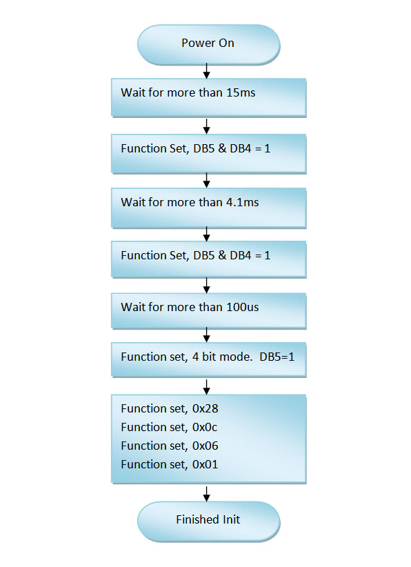
LCD Initialisation
The following flowchart shows the sequence to initialise the LCD, note that the waiting time is different for each different LCD manufactured by different company. Function LCD_Init() in LCD.C implements the initialisation flowchart.
LCD Pulse Enable
Each and every command or data written or read from the LCD controller will need to be pulsed on the LCD controller’s enable pin. The microcontroller (host) basically turn the enable pin HIGH, delay and then LOW. The delay time is depending on the LCD modules. Each module has different delay timing, refer to the LCD module’s datasheet.
void LCD_PulseEnable(void)
{
// NOTE: Enable pulse width greatly depending on the different LCD module.
LCD_EN=1; // Set enable high
Delay1KTCYx(10); // Delay1KTCYx(10)=0.83ms
LCD_EN=0; // Set enable low
Delay1KTCYx(10); // Delay1KTCYx(10)=0.83ms
}
LCD Write Byte
In order to write a byte to the LCD module in 4 bit mode, the byte need to be separated into nibble, the high nibble (D4-D7) will be sent first, and then follow by the low nibble.
The microcontroller will need to tell the LCD if the data to be written is COMMAND or DATA by controlling the RS pin LOW or HIGH respectively.
void LCD_WriteByte(unsigned char reg, unsigned char data)
{
LATC=0; // setting PORTC latch to 0
LCD_RS=reg; // configure LCD RS as command / data
LCD_EN=0; // setting LCD enable pin low
LATC |= (data & 0b11110000); // data high nibble
LCD_PulseEnable();
LATC=0; // setting PORTC latch to 0
LCD_RS=reg; // configure LCD RS as command / data
LCD_EN=0; // setting LCD enable pin low
LATC |= (data << 4); // data low nibble moved to PORTC high nibble
LCD_PulseEnable();
}
Example code for MonkeyBUS
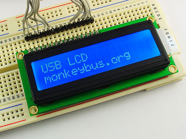
The easiest way to test the LCD is to try our precompiled code. Follow the instructions from Getting Started, download the complete project files from our repository and burn the testing firmware into MonkeyBUS. Connect MonkeyBUS to the USB port of a PC, as soon as it is connected, the default splash screen will be displayed.
From Window’s device manager, locate the installed COM port. Run Hyperterminal or any terminal program. Open the installed COM port with 115200 baud rate, 8 bit, Non parity and 1 stop bit. Start typing in the terminal program and the LCD module will display the same character. Pressing enter key will clear the LCD screen and move the cursor back to line 1 position 1.
Final Thoughts
This tutorial shows the basic way to interface with the HD44780 LCD module, the method ignores the LCD busy bit and assumed the LCD will be ready in a predefined delay. If more IO pins are available on the microcontroller, a better way is to connect 1 IO pin to the READ/WRITE pin of the LCD module and use the READ command from the LCD to check for the BUSY bit.
Next we will look at implementing a serial protocol compatible with LCD Smartie for more advance LCD display showing news, emails, weather, CPU load and even WinAMP spectrum analyser.
Downloads
HD44780 Datasheet
USB HD44780 LCD Source code