HIH6130 Humidity & Temperature Sensor Interface

Description
The HIH6130 humidity and temperature sensor was designed with energy efficiency in mind. It has the ability to wake up quickly from sleep mode and start humidity and temperature conversion. When not in used, it goes to sleep consumes minimum power, which is great for energy conscious applications. It uses I2C digital interface for communication, which is also known as two-wire-interface. The advantage of I2C is that it is a lot less susceptible to noise over short distance, typically within few meters to ensure reliability and accuracy.
For more information on HIH6130, checkout the download section at the end of this article, it tells you everything you need to know about its I2C interface and timing requirements for this device.
Features
- Read and interpret HIH6130 data
- UART emulation data output
- LED indicator
Parts and Tools List
- MonkeyBus microcontroller board
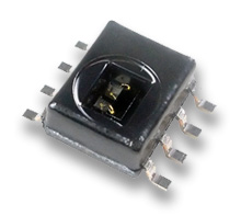
- HIH6310
- ARIES 08-350000-11-RC breadboard adaptor
- 2 x 2.2k Resistors
- 1 x 0.22uF Capacitor
- 1 x 0.1 uF Capacitor
Now, let's put all these parts together.
Hardware
The following sections shows the step by step guide on how the parts are configured and wired up.
MonkeyBUS
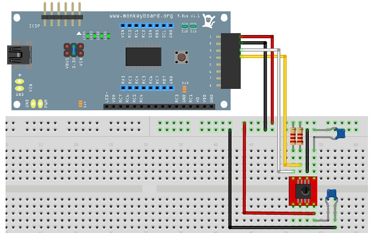
Most environmental sensors run off 3.3V. Even though the HIH6130 is capable of using both 3.3V and 5V, it is best to configure the MonkeyBUS to supply 3.3V on SV1 so that other sensor can use the same bus in the future. Seen below image for jumper settings. Set 3.3V jumper and SJ1 and SJ2 pull-up for I2C.
HIH6130 Wireup
Next, wire up the sensor up as per HIH6130 datasheet using the parts mentioned earlier. An example of a setup is shown here. The pin description of the HIH6130 is shown in the following section.
HIH6130 Pin Description
|
Pin No |
Symbol |
Function |
|
1 |
Vcore |
connect via 0.1 μF to ground |
|
2 |
Vss |
supply ground |
|
3 |
SCL |
I2C clock |
|
4 |
SDA |
I2C data |
|
5 |
AL_H |
alarm output high |
|
6 |
AL_L |
alarm output low |
|
7 |
NC |
not connected externally |
|
8 |
Vdd |
supply voltage, connect via 0.22 μF to ground |
Software
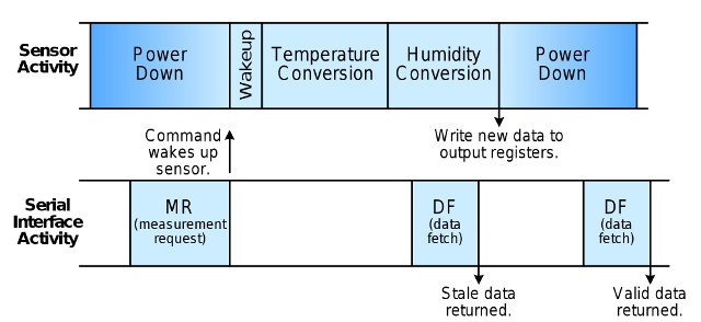
The HIH6130 wakes up when measurement request is received. Once awake, it will take 36.65ms to convert humidity and temperature. The data can be read using the data fetch command. If read too early status bits will return stale data. Diagram below shows the relationship between the sensor and commands sent by the master.
This software example is a modification of the Microchip USB Serial Emulator example plus the following additions:
- I2C driver
- Delay timer
- Output to serial port emulator
Readings from the sensor are pumped to the USB serial emulator port at 19200pbs. Format:
H<Humidity %>T<Temperature C>\r\n
Setting I2C
The function
InitializeI2C();
sets the MonkeyBUS as master , enable Synchronous Serial Port and sets the clock to 100kHz. The frequency is set by the SSPADD register. The formula below is used to calculate the SSPADD value:
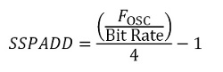
Where Fosc is the operating Clock which is the crystal frequency multiplied by the PLL. The PLL is configured to be 4 and the crystal frequency on the MonkeyBUS is 12MHz. Therefore, the operating clock is 4 x 12MHz = 48MhHz and for 100kHz I2C clock, SSPADD is set to 119.
The software then enters an infinite loop to read and display humidity and temperature reading from the HIH6130 using the following functions:
GetHihReading (&humidity, &temperature);
PrintHihData (humidity, temperature);
Setting Up Delay
In the GetHihReading function, a delay is used to wait for the sensor to be in acquisition mode and wait once again for valid data. To delay for a specific amount of time use one of the following functions:
Delay1TCY(n) // Delay one instruction cycle
Delay10TCYx(n) // Delay in multiples of 10 instruction cycles
Delay100TCYx(n) // Delay in multiples of 100 instruction
Delay1KTCYx(n) // Delay in multiples of 1,000 instruction
Delay10KTCYx(n) // Delay in multiples of 10,000 instruction cycles.
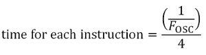
The n variable is a multiple of instructions. The delay is calculated in the following way:
It takes 4 clock cycles for each instruction, therefore one seconds will execute 12 million instructions. The time for each instruction is the invert of 12 million which is 83ns.
The HIH6130 takes 36.65ms for conversion, so the total number of instruction requires to achieve this delay is calculated by:

To avoid reading a lot of stale data, we extend the delay to 500000 instructions, therefore a value of 50 is passed to the delay function
Delay10KTCYx(50) // Delay in 50 x 10,000 instruction cycles.
Output to Serial Emulator
Alright, almost there! Once the coversion is complete, the data is printed to the serial port using the function:
PrintHihData ();
It populates the USB_Out_Buffer with data. The function:
ProcessIO();
checks the buffer and pass it to the USB serial port emulation stack. But beware of the the buffer size and try not to overload it with data. The CDC_DATA_OUT_EP_SIZE defines the buffer size.
And that is it! Power on the MonkeyBUS and see humidity and temperature reading pumping through your serial port.
Final Thoughts
This example though simple, but it demonstrate the use if I2C and how to communicate with the HIH6130. Future tutorial will show how to have a series of environmental sensors linked up on the same I2C bus and configuring them to set of alerts and can be used as a standalone device. So stay tuned.
Downloads
PIC18F14K50 I2C Datasheet
HIH6130 Datasheet
HIH6130 I2C Datasheet
HIH6130 for MonkeyBUS Firmware source code